DIY CNC plasma cutter
A custom-built CNC plasma cutting machine,
designed and built from scratch.
Status: Ongoing
Started: 2026
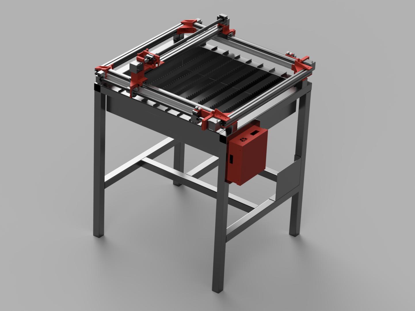
PROJECT OVERVIEW
This project started with a simple goal: build my own CNC plasma cutter from scratch.
Rather than buying a complete machine, I wanted to design and build the mechanical structure, motion system, electronics and control system myself. The project has been a combination of steel fabrication, mechanical design, electronics, CNC control and a fair amount of troubleshooting along the way.
The result is a custom-built CNC plasma cutter designed to cut sheet metal while giving me the flexibility to modify and improve the machine as I learn more.
Why Build One?
A CNC plasma cutter is a great combination of several areas of engineering that I enjoy working with. The machine requires everything from designing a rigid steel frame and linear motion system to controlling motors and integrating a plasma cutter.
Building the machine myself also means that I am not limited to the specifications of a commercial machine. I can experiment with different solutions and continue upgrading it over time.
The Machine
The CNC plasma cutter is built around two separate frames, each with a different purpose.
The Table
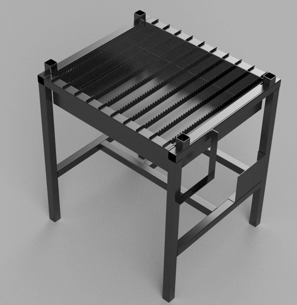
The first frame is the main table of the machine. It provides the rigid structure that supports the workpiece and the cutting system.
The table is built with an integrated water bath, which sits underneath the cutting area. The water helps reduce smoke and dust produced during plasma cutting, while also helping to absorb some of the heat generated during the cutting process.
The table also contains the machine’s mains power installation, providing a central point for supplying power to the different electrical systems of the machine.
The CNC Frame
The second frame is the CNC motion structure. This is the part of the machine responsible for moving the plasma torch across the material.
The two frames are separate, allowing the cutting table and the CNC mechanism to be constructed and modified independently.
The CNC frame carries the motion system for the X and Y axes, together with the plasma torch and its mounting system. The machine can therefore move the torch precisely across the workpiece according to the programmed toolpath.
Keeping the machine divided into two main structures also makes it easier to work on individual parts of the system and leaves room for future upgrades.
Control System – Smoothieware & bCNC
Control System Overview
The CNC plasma cutter is controlled using a SKR 1.3 controller board running Smoothieware. For sending G-code and controlling the machine, I use bCNC as the interface between the computer and the CNC controller.
The complete control system can therefore be divided into three main parts:
Computer
- bCNC
- G-code generation and control
- USB connection
CNC Controller
- SKR 1.3
- Smoothieware
- Stepper motor control
- Limit switch inputs
- Plasma control interface
Plasma System
- Plasma cutter
- Optocoupler isolation circuit
- Plasma start signal
- Cutting torch
SKR 1.3 Controller board
The main controller for the machine is a BigTreeTech SKR 1.3 board.
Although the SKR 1.3 was originally designed primarily for 3D printers, it is well suited for this project because it provides stepper motor drivers, configurable inputs and outputs, and support for Smoothieware.
The controller is responsible for controlling the movement of the machine. It receives G-code from bCNC and converts the commands into step and direction signals for the X and Y stepper motors.
The SKR 1.3 also provides the inputs used for the machine’s limit switches and other control functions.
Smoothieware
The SKR 1.3 runs Smoothieware, an open-source CNC controller firmware.
Smoothieware handles the low-level control of the machine. It interprets the G-code received from bCNC and controls the stepper motors according to the configured machine parameters.
The configuration is done through the Smoothieware configuration file, where parameters such as steps per millimeter, maximum speeds, acceleration and input/output functions can be defined.
Using Smoothieware also makes the controller highly configurable, which is particularly useful for a custom-built machine where the hardware does not necessarily follow a standard CNC configuration.
bCNC
bCNC is used as the main computer interface for the machine.
I use bCNC to load and send G-code files to the SKR 1.3. It also provides a graphical interface for controlling the machine manually, setting the machine position and monitoring the machining process.
The general control chain is:
bCNC → USB → SKR 1.3 → Smoothieware → Stepper Drivers → Motors
This keeps the computer responsible for generating and sending the toolpath, while Smoothieware handles the actual real-time control of the machine.
Plasma Start
Instead of connecting directly to the plasma cutter’s internal power circuitry, I modified the original handheld torch control.
The plasma cutter normally uses a switch on the handheld torch to start and stop the cutting arc. I modified this circuit so that the same function can be controlled electronically by the CNC controller.
The original torch ON/OFF control is connected to the SKR 1.3 through an interface circuit. This allows the CNC controller to effectively operate the same function as pressing the trigger on the handheld torch.
The plasma cutter is then controlled directly from the G-code using standard CNC commands:
- M3 — Start the plasma cutter
- M5 — Stop the plasma cutter
This means that when bCNC sends a cutting program to the machine, Smoothieware can automatically start the plasma cutter at the beginning of a cut and shut it down when the cut is finished.
This was a relatively simple way of integrating the plasma cutter into the CNC system while still using the original start/stop functionality of the machine.
Electrical Isolation
Connecting the plasma cutter directly to the SKR 1.3 was not considered safe because the plasma cutter can generate significant electrical noise and voltage spikes during operation.
To protect the controller, I built a small interface circuit using an optocoupler between the SKR 1.3 and the plasma cutter.
The optocoupler provides electrical isolation between the controller electronics and the plasma-control circuit. The SKR 1.3 therefore does not have a direct electrical connection to the plasma side of the circuit.
The basic principle is:
SKR 1.3 → Optocoupler → Plasma Start Circuit → Plasma Cutter
This helps protect the relatively sensitive controller electronics from voltage spikes and electrical noise generated by the plasma cutter.
Building this interface was an important part of making the control system reliable. Plasma cutters are electrically noisy devices, and separating the control electronics from the plasma circuit reduces the risk of interference or damage to the controller.
Future Improvements
Some of the ideas for future development include:
- Motorized Z-axis
- Custom Torch Height Controller
- Arc-voltage measurement
- Automatic material height sensing
- Improved torch mounting
- Better cable management
- Improved machine enclosure
- More advanced CNC control
- Automatic probing / zeroing
- Improved cutting accuracy and repeatability
The machine will probably never be completely “finished”. There will always be something that can be improved, redesigned or experimented with.
And that’s really the point of the project.
 NordProtex